In electronic devices, the filters are the circuits that allow desires frequency components and blocks all other frequency components of a signal. For example, in radio or tv, a tuning filter circuit rejects unwanted frequencies by allowing only the desired channel. Filter circuits are divided into four types based on the range of frequencies that the circuit would allow while blocking all other frequencies. They are low pass filters, high pass filters, bandpass filters, and bandstop filters. These types of filter circuits come under the passive filter category because the passive elements resistor, capacitor, and inductors are used in the circuit. This article describes the low pass filter using op-amp (active element), which is also called an active LPF.
Definition: The filter circuit which allows only low pass frequency components and blocks all other higher frequency components is called a low pass filter. The name LPF itself indicates low range frequency.
This type of filter circuit allows the frequency components of the signal less than the cut of the frequency range of a signal. The gain of the low pass filter is inversely proportional to the frequency. If the frequency of an input signal increases, the gain of the circuit decreases and also becomes zero at the transition band end-stage. So, the bandwidth is also limited. But, in practice, the LPF allows the low range frequency components of a signal even it reaches after the cut off frequency.
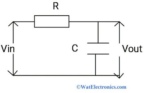
The low pass filter circuit diagram is shown below. It contains passive elements resistor and capacitor connected in series with an applied input voltage across the resistor and its output voltage is obtained across the capacitor.
Low Pass Filter Circuit
The first order low pass filter is of two types. They are
This type is a simple RL circuit as shown below. When the frequency of a signal increases, then the impedance of the inductor increases. This results in blocking of high-frequency signals and allow only low frequencies of a signal through the circuit.
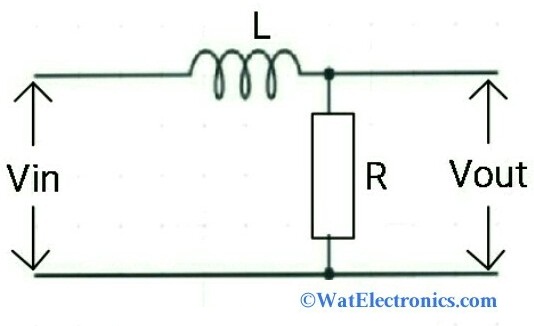
Inductive Type LPF
This type is a simple RC LPF circuit as shown in the above figure. It is also called a simple Low pass filter circuit. When the frequency of the signal increases, then the impedance of the capacitor decrease and results in blocking if high frequencies of the signal and allows only low frequencies of the signal through the circuit.
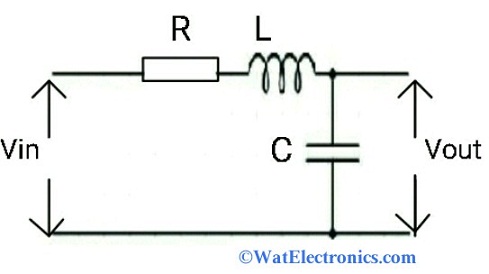
The second-order low pass filter circuit is an RLC circuit as shown in the below diagram. The output voltage is obtained across the capacitor. This type of LPF is works more efficiently than first-order LPF because two passive elements inductor and capacitor are used to block the high frequencies of the input signal.
 Second Order Low Pass Filter" width="373" height="209" />
Second-Order Low Pass Filter
The LPF using op-amp is referred to as an active low pass filter. It is very easy to design a low pass filter circuit using op-amp without the use of electrical components like inductor which is very difficult to design and also expensive. Operational amplifiers (op-amps) are used in the filter circuits to achieve amplification of the signal and also controls gain. Op-amps change the frequency response and produce better voltage gain within its feedback. It also has higher input impedance, lower output impedance, low noise, and performance level is high.
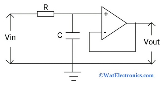
Low Pass Filter using Op-Amp
The operation of a basic LPF (passive filter) circuit and low pass filter using Op-amp (active filter) is the same except that an op-amp is connected to an RC filter circuit. It may be inverting or non-inverting op-amp. The circuit diagram of the low pass filter using op-amp is shown below.
The first order active LPC circuit is designed with a capacitor, resistor, and an op-amp as shown below. The inverting or non-inverting op-amp is connected to the RC circuit to obtain an active LPF circuit. The amplitude output signal obtained from the RC low pass filter circuit is smaller than the amplitude of the input signal. This low-frequency signal of the RC LPF circuit is fed to the Op-amp as the input to achieve amplification, high power gain, and stability to the filter. Here the op-amp acts as buffer circuit like voltage follower with a DC gain= 1.
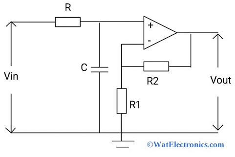
First Order Active LPF
As the frequency of the input signal increases, it passes through the capacitor to increase the amplitude of the output signal for amplification associated with the passband gain. At low frequencies, the output signal of the RC circuit flows directly through the op-amp for amplification.
The voltage gain is given as DC = 1+R2/R1
The second-order active LPF circuit is designed by cascading of two RC low pass filter circuits with an op-amp. Here Op-amp acts as a voltage controlled source amplifier. The frequency response is the same as the first order active LPF except that the stop-band gain is twice of first-order active LPF i.e, 40dB/decade. The cascading of filter circuits forms higher-order filters whose gain is the product of each RC LPF circuit.
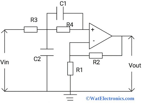
Second Order Active Low Pass Filter
We know that the gain of the first order active LPF is -3dB at the cut-off frequency. So, the gain of the second-order active LPF is -6dB at the cut-off frequency i.e, gain increased twice.
The gain is calculated as
Av = Av1 x Av2
The total gain in dB
Av = Av1 + Av2
The circuit diagram of second-order active LPF is shown below.
A low pass filter calculator is the calculation of cut-off frequency, voltage gain, and the phase shift of the LPF circuit.
Please refer to this link for Low Pass Filter MCQs
From the LPF circuit diagram (RC circuit), we can observe that ‘Vi’ is the applied input voltage
‘Vo’ is the output voltage
By the transfer function of the circuit, we get
H(s) = V₀(s)/Vᵢ(s) = (1/sC)/(R+(1/sC))
Since Vo(s) = 1/sC
Vi(s) = R + 1/s
H(s) = 1 / (1+sCR)
Then the above equation becomes
H(jω) = 1 / (1+jωCR)
We can calculate the magnitude of the transfer function from the above equation. It is given as
|H(jω)| =1 /√[1+(ωCR)^2]
The magnitude of the transfer function is calculated with the help of ‘ω’ i.e, angular frequency
If ω = 0 then the magnitude of the transfer function = 0
If ω = 1/ CR then the magnitude of the transfer function = 0.707
If ω = infinity then the magnitude of the transfer function = 0
To calculate the gain and phase shift of the LPF,
Consider ω = 1/RC and ω = ωc for the above equation
Then the above equation becomes,
Gain |H(jω) = 1 / √[1+(ω/ωc)^2]
Since the total voltage gain is,
Av = 20log10 (Vout /Vin) in dB
Consider f = operating frequency and fc = cut-off frequency
The phase shift of the LPF circuit is
Φ = tan⁻¹ (ω/ωc)
The cut-off frequency of the LPF circuit is,
fc=1/2πRC
The phase shift is,
Φ ⁼ tan⁻¹(2πfRC)
The equation of capacitive reactance in ohms of the LPF circuit is given as
Xc = 1/2πfC
Where C = capacitance in Farads
f= operating frequency in Hz
The frequency response characteristics are drawn between gain (dB) and frequency (Hz).
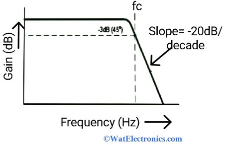
At the low frequencies, the gain of the LPF is higher than the passband gain of the filter
At high frequencies, the gain of the LPF is less than its passband gain and it falls to -20dB
As the frequency increases, the output voltage falls 70.71% below the input voltage.
The low pass filter applications include the following.
Please refer to this link to know more about Band Pass Filter MCQs, FIR Filter MCQs and High Pass Filter MCQs
Thus, this is all about an overview of the low pass filter circuit using an op-amp, a basic LPF circuit, first-order active LPF, second-order active LPF, low pass filter calculator, and applications. The purpose of the LPF is to allow only low-frequency signals and block high-frequency signals. Here are a few questions for you : What are the advantages of LPF using Op-amp? What is Band Stop Filter?
Filed Under: Electronics Tagged With: Filter